Analyze & Measure
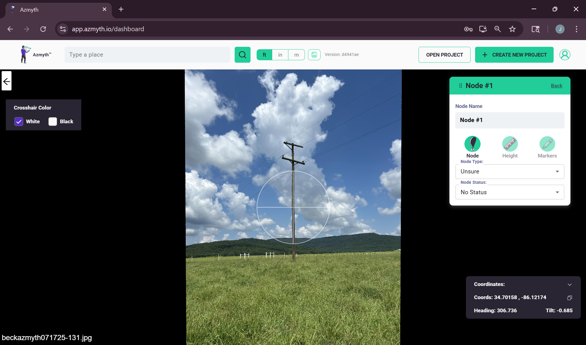
Once your images are captured in the field, the next step is to review, measure and export in the azmyth.io web app.
This section explains how to start a project, create a node, perform measurements, verify accuracy, and export your results.
Azmyth supports iPhone imagery (Azmyth on Foot) as well as 360° imagery.
1. View Azmyth on Foot Nodes in Azmyth Web
Back at your desk (or on a laptop in the truck), follow these steps to view the node(s) you collected:
- Go to azmyth.io and log in with your account.
- Create or open a project.
- Locate the node(s) you captured.
- Click the node image to open the Azmyth measurement viewer.
- The viewer will display all node-related content, including:
- The main pole photo
- The node position plotted on the map
- Any supplemental photos (equipment details, tags, backside images, etc.)
- Any attributes or notes added in the field
2. Correcting Nodes with Inaccurate Position Data
Some nodes may have incorrect position data due to field constraints. For example, when a pole is located inside a dense thicket or behind an obstruction, and the RTK receiver cannot be placed directly on the structure. In these cases, you can manually correct the node’s position in the Azmyth web app.
How to Manually Correct a Node Position
- Open the node by clicking its image in the node list.
- Create and save the node (if not already saved), then return to the satellite/map view.
- In the node list on the right, click the three dots next to the node’s name and select Move.
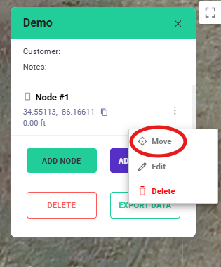
Captured locations can be adjusted using the "Move" function in Azmyth. - A bouncing marker will appear on the map. Drag and drop it onto the correct pole location.
- The new coordinates will save automatically. You can then reopen the node to continue measurement and analysis.
Notes
- This method is especially useful when you’ve loaded in waypoint overlays showing expected pole locations.
- While manual adjustments won’t achieve centimeter-level RTK precision, they allow you to produce accurate positional estimates for inaccessible nodes.
- If a waypoint overlay is present for this project, we recommend turning that waypoint Blue.
3. Triangulating Objects with 360° imagery
Azmyth allows you to determine the position of objects by triangulating their location using 360° imagery.
How to Triangulate an Object
- Open an image node by clicking on it in satellite view.
Note
360° images are a darker shade of purple than iPhone images.
- Once the image loads, identify the object you want to triangulate.
- Point your crosshairs at the object center-mass and either click "Set Position 1" or hit the space bar.
- Navigate to a second image by clicking on the image's name or using the "S" or "D" keys.
- Shoot the object again, placing the crosshairs on the same center-mass location.
- You must shoot the object from at least three images to create a node. Your accuracy will appear in your side menu once you do so.
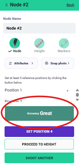
The accuracy of your triangulation is shown on the menu on the left side of your screen.
Note
Accuracy ranges between Great, Good, Fair, and Bad
- Repeat from additional images if available to improve accuracy.
Azmyth will automatically triangulate the object’s position based on the intersecting sightlines from each image.
Best Practices for Accurate Triangulation
- Try to point your crosshairs at the base of your object so that you shoot relatively close to the same point.
- Aim for the true center of the object, not edges or shadows.
- Avoid shots taken from nearly the same camera position, as this reduces positional accuracy.
- Additional shots improve confidence, especially for objects farther from the camera path.
4. Measure the Node
The measurement tools allow you to extract attachment heights, clearances, and other spatial details directly from the calibrated photo.
Once you've created a project and selected an iOS image or triangulated a node, you are ready to take measurements.
Note
The following steps are the same for objects triangulated with 360° imagery or shot with Azmyth on Foot.
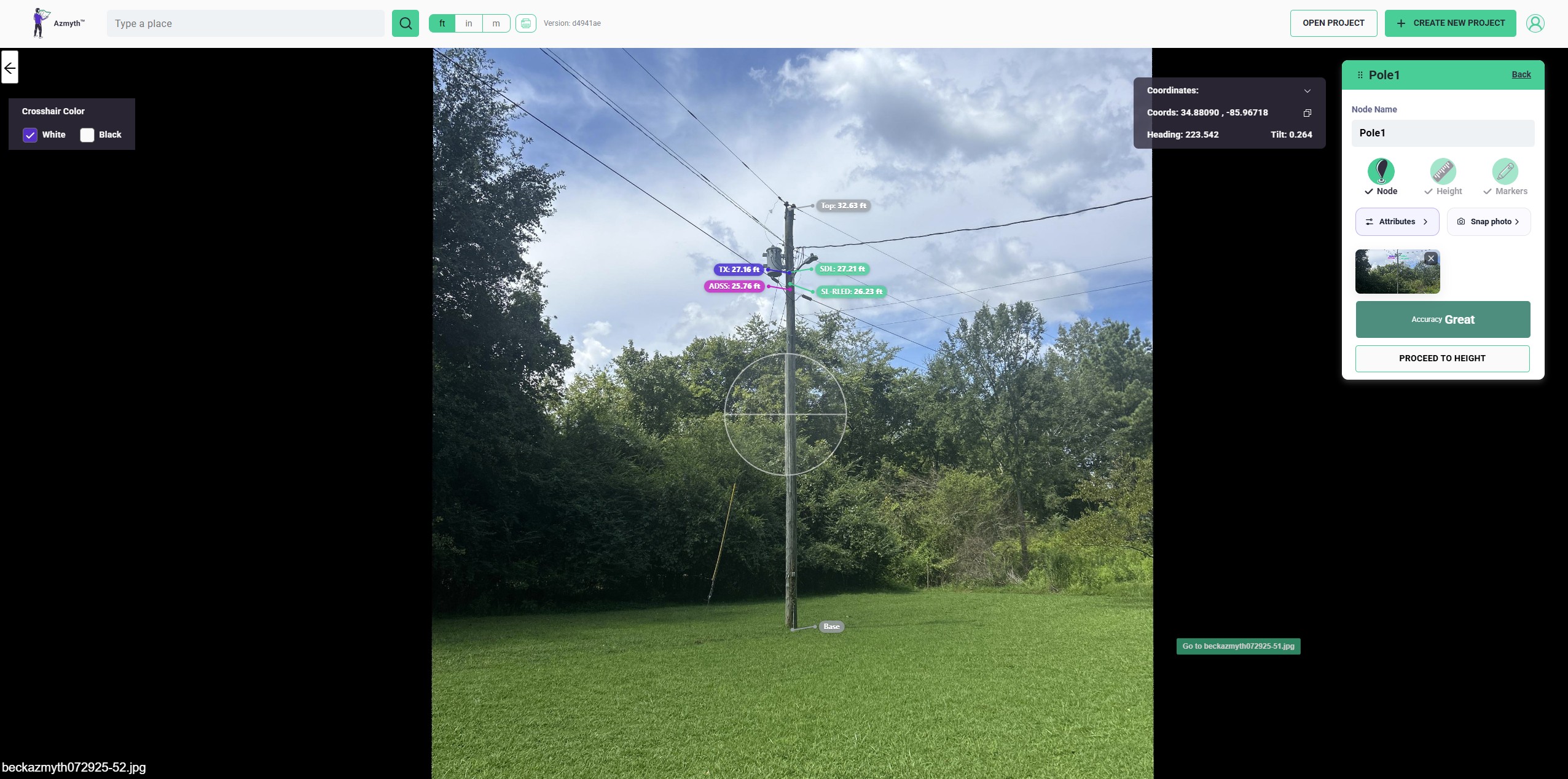
Measurement Steps
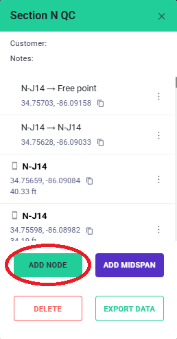
1. Add a Node
- Click Add Node on the right side of your screen.
- Enter a name in the Node Name text box.
- Your newly created node will open in the measurement viewer.
2. Select a Measurement Tool
Use the toolbar to choose the correct tool:
- Height Tool — measure the pole height.
- Markers Tool — measure attachment heights (power, neutral, comm, etc.).
- Anchor Tool — connect attachments to an anchor or down guy.
- Attributes Tool — assign a node type, status color, or other metadata.
3. Measure Pole Height (Height Tool)
- Click Height in the toolbar.
- Use the crosshairs to establish your vertical reference:
- Point at the ground line and click Mark Bottom.
- Move the crosshairs to the very top of the pole.
- Click Mark Top.
- Confirm the height displayed in the measurement panel.
Pole height must be measured first, since all attachment measurements are referenced to this calibration.
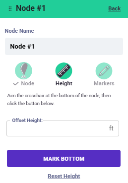
This sets the vertical calibration for all subsequent marker measurements.
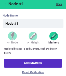
4. Measure Attachment Heights (Markers Tool)
- Click Markers in the toolbar.
- Select the attachment type (e.g., Primary, Secondary, Neutral, COM1, COM2, Fiber, Riser, etc.).
- Move the crosshairs to the center of the attachment you want to measure.
- Click "Add Marker"
- Repeat for all desired attachments on the pole:
- Verify each marker’s height in the sidebar list.
Each marker automatically uses your pole calibration to calculate its height above ground.
5. Add Anchors or Guy Measurements
Note
Upon creating an attachment, you have the option to attach to an anchor. This anchor must be collected separately in the field, following the same steps as collecting any other node."
- Select the attachment that connects to the anchor (e.g., down guy point).
- Click Attach to anchor.
-
Azmyth will draw a connection between the attachment marker and the anchor point.
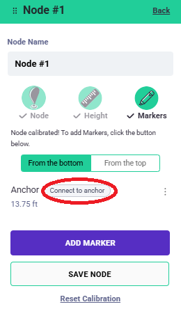
Attach an anchor to your pole with this tool.
6. Add Node Attributes (Attributes Tool)
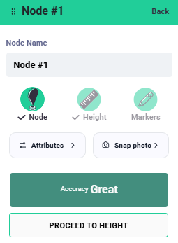
- Click Attributes in the Node toolbar.
- Assign:
- Node Type (e.g., Pole, Anchor, Midspan, Riser pole, etc.)
- Node Status Color (Green, Yellow, Red, Blue)
- Any additional metadata desired for your workflow.
- Review all entries for accuracy.
7. Save Your Node
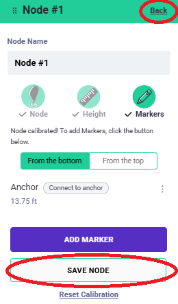
- Click Save Node at the bottom of the measurement viewer.
- Your height, markers, anchors, and attributes are now stored in the project.
- Saving preserves your work for export, engineering review, and reporting.
Note
You can also simply click Back in the top right of your node measurement tool to save your work and exit back to project view.
Measurement Best Practices
- Verify the ground reference before measuring clearances.
- Re-check points that are partially obscured (trees, transformers, shadows).
- Use supplemental photos to confirm equipment type or attachment height.
5. Connect Nodes and Create Midspans
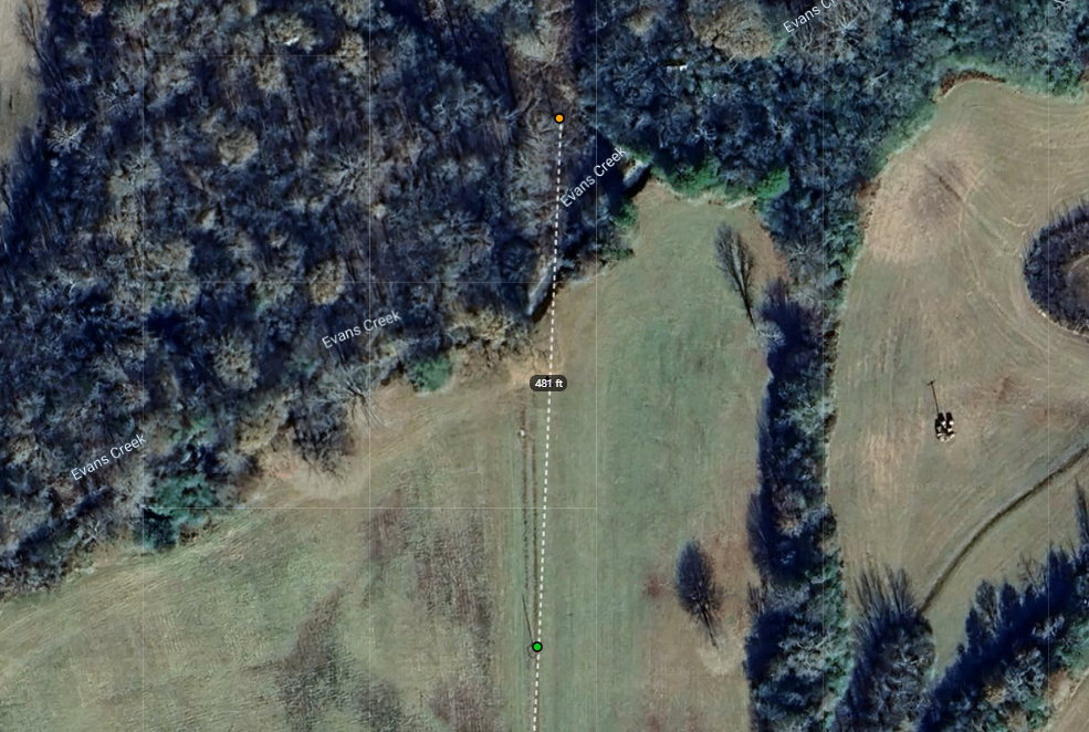
Once your nodes are measured, you can connect them with midspans to create complete distribution or communication line maps in Azmyth. Midspans help define the physical relationship between poles, enabling clearance evaluation and visual continuity of the network.
Add Midspans Between Nodes
- Open your project in Azmyth web.
-
Select the Midspan Tool from the toolbar.
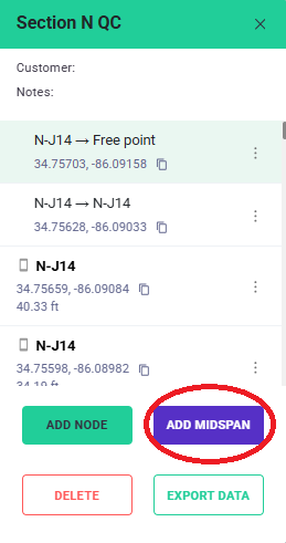
Click the purple midspan button to start the workflow. -
Click the origin node (e.g., the pole where the span begins).
-
Click the destination node (the pole where the span terminates).
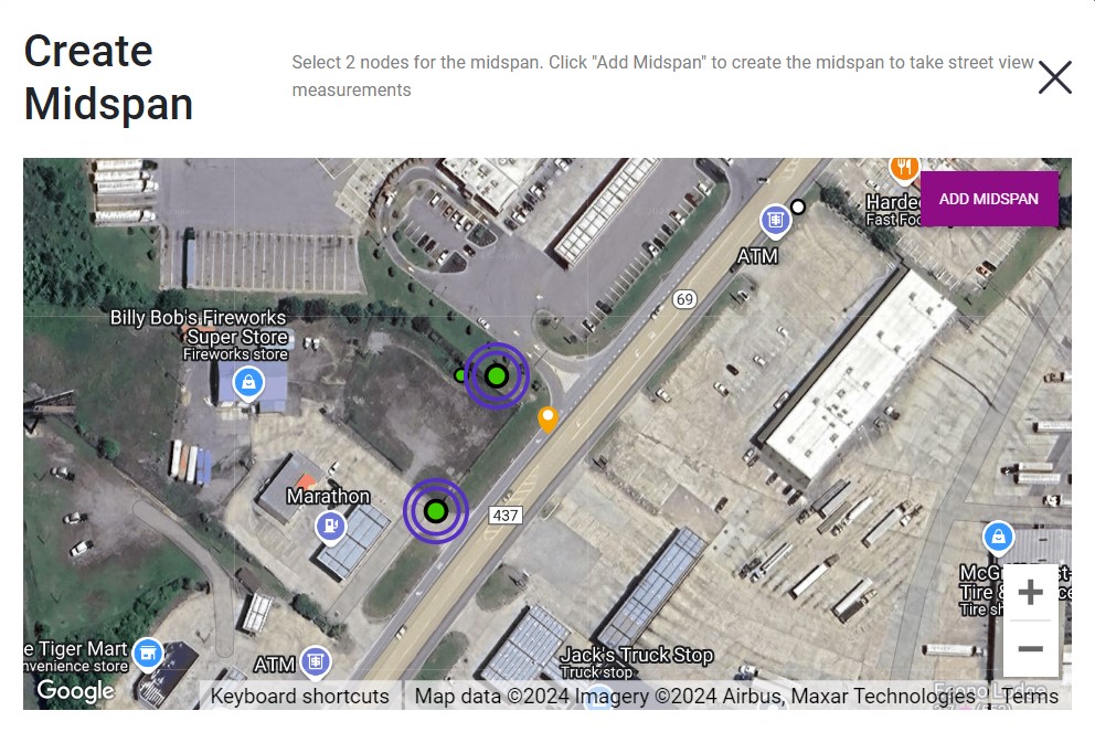
Select the nodes you wish to connect. -
Azmyth will draw a calibrated span line between the two poles.
Note
You can create spans between node in your Azmyth project and KML overlay node.